SIMATIC SWITCHGEAR & SIMATIC SYNCHRONIZATION PANEL
Single-line and control schematics, enclosure layout, component coordination, metering, protection and breaker interfaces — engineered around the approved project requirements.
POWER & SYNCHRONIZATION · PANELS + SOFTWARE
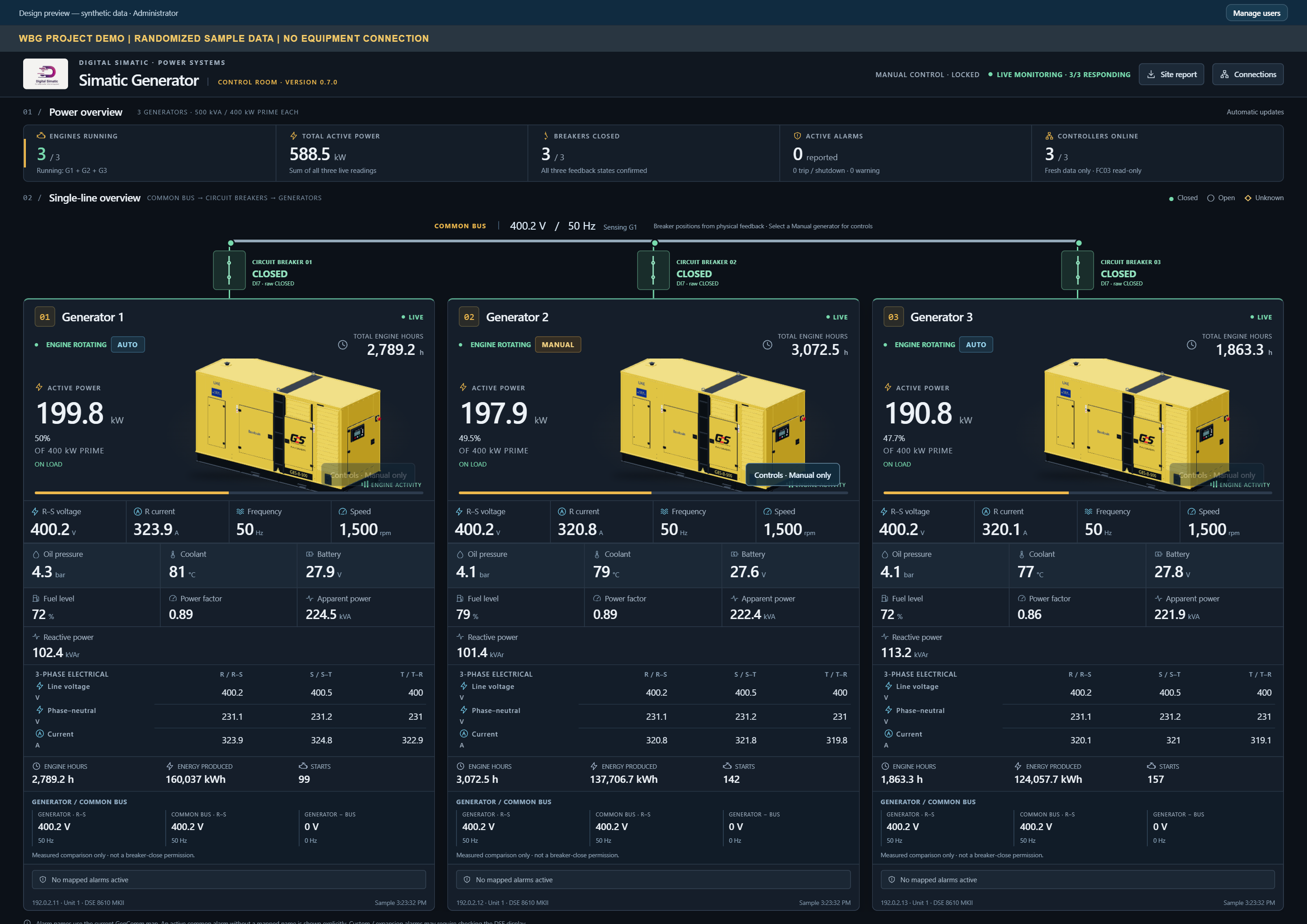
SIMATIC GENERATOR is the monitoring and supervisory software for our SIMATIC SWITCHGEAR and synchronization panel systems. The Windows application brings generator measurements, operating modes, breaker feedback and alarms into one view, with DSE8610 MKII / Modbus TCP integration and separately guarded manual requests in version 0.7.0.
POWER & SYNCHRONIZATION
SIMATIC SWITCHGEAR and synchronization panels are the engineered electrical systems. SIMATIC GENERATOR brings their measurements, status and operator workflows into one software interface.
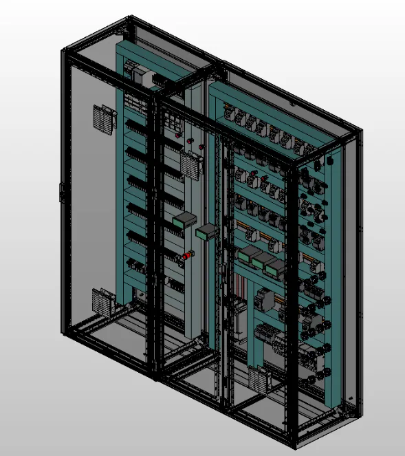
Single-line and control schematics, enclosure layout, component coordination, metering, protection and breaker interfaces — engineered around the approved project requirements.
Synchronization, load sharing, electrical interlocks and protection remain with the equipment controllers and engineered panel system. Software requests do not bypass these functions.
One operator view for available measurements, operating modes, breaker feedback, load assessment and contextual alarms, with guarded manual requests where commissioned.
Electrical design → panel assembly & wiring → software integration → project-specific testing & commissioning.
01 / SIMATIC GENERATOR SOFTWARE
Choose a workflow to explore the supplied product screens. Every screen stays complete, with a full-size view for the details.
Actual software interface · Randomized demonstration data · No equipment connection. These images do not establish installed sensors, commissioned manual control or live site performance.
System monitoring
A common-bus single-line view connects three individual generator cards, keeping measurements and status beside the equipment they describe.
02 / PRODUCT CAPABILITIES
A clear software layer between equipment information and everyday operating decisions.
A common-bus overview and per-unit 3D presentation connect generator state, mode and breaker feedback in one operator page.
View available voltage, current, frequency, power, RPM, pressure, temperature, fuel and battery readings from each controller.
Compare measured load with the configured prime rating, alongside engine hours, energy and start counters where available.
Equipment-level warnings and trips remain in context, with clear last-confirmed status when communication is interrupted.
Valid zero, unavailable and stale readings are kept distinct. Retained engine-hour snapshots are labelled separately from live readings.
Local account permissions and separately guarded manual requests support authorized operation after site-specific verification.
CALCULATED INSIGHT
SIMATIC GENERATOR calculates an application load percentage from measured active power and the configured prime rating. It also displays generator-to-bus voltage and frequency differences as operating information.
This is a load calculation, not a forecast, an available-capacity guarantee or permission to close a breaker. The application does not estimate engine hours while disconnected; native synchronization and load sharing remain with the controllers.
03 / HOW IT WORKS
The local application acquires available measurements and feedback from the three configured DSE8610 MKII controllers over Modbus TCP.
The dashboard presents data freshness, generator and bus measurements, load percentages and contextual alarms for operator assessment.
Where version 0.7.0 has been commissioned, an authorized administrator can request one manual action after the required state and permission checks.
The controller remains responsible for its native sequence and protection. A request acknowledgement is not proof that an engine or breaker changed state.
The supplied dossier documents package 0.7.0 and an installed 0.6.0 record. Installation and commissioning of 0.7.0 are not established by the screenshots.
Controller identity, loaded configuration, available signals and breaker feedback must be verified against the installed equipment and approved site procedure.
Commands remain locked until site-specific commissioning and authorization. Local controls, emergency stops, synchronization and electrical protection remain with the engineered system.
04 / ENGINEERING CONTEXT
Examples of panel implementation within the same Power & Synchronization sector. These field photographs are separate from the software demonstrations and do not establish which application version is installed.
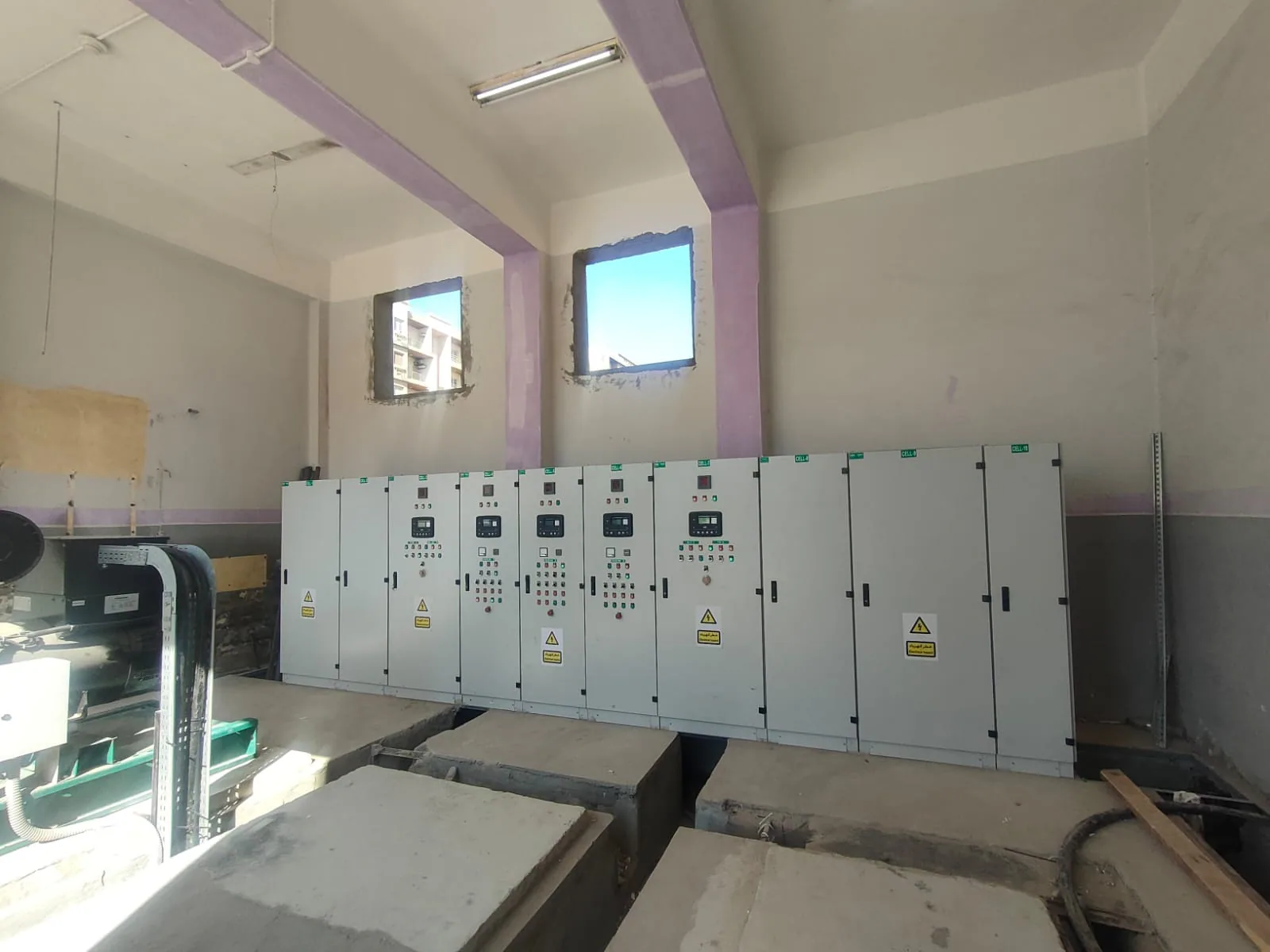
A panel reference from our power-systems portfolio, showing the physical engineering behind an integrated generator installation.
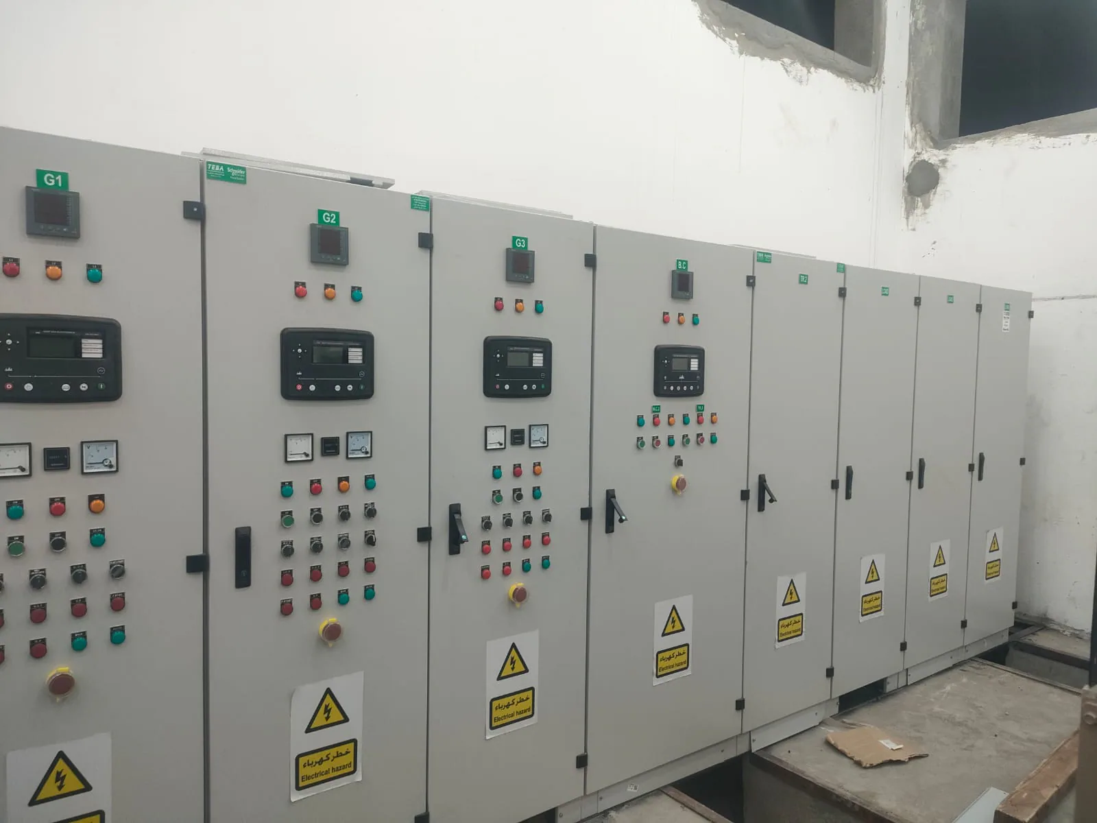
Field panel work complements operator software; the electrical design and equipment controllers define the approved operating arrangement.