Generation & conversion
Follow PV output and string information alongside the hybrid inverter or PCS operating state.
SOFTWARE BY DIGITAL SIMATIC
Solar generation, battery storage, power conversion and AC sources — connected through one operator experience. Select an operating scenario and follow the energy from source to site.
INTERACTIVE SYSTEM OVERVIEW
Solar PV → PCS → Site load + battery
The solar array feeds the hybrid PCS. Available power supplies the site, while surplus energy can charge the battery. The approved AC source remains on standby.
GENERATION / Solar PV
Scenario state: Generating
PV production, string current and irradiance belong together. SIMATIC SOLAR brings the generation picture into the same operating view as the rest of the plant.
Illustrative energy paths, not an electrical wiring diagram. Final equipment, operating logic and permissions are engineered for each project.
01 / INSIDE THE PRODUCT
Choose a workflow to explore the supplied product screens. Every screen stays complete, with a full-size view for the details.
Demonstration front end: the supplied screens use illustrative values. They are not evidence of live telemetry, a connected historian or delivered notifications. This website does not connect to or control equipment.
Energy & equipment
Understand the energy path before opening an individual asset.
02 / PRODUCT CAPABILITIES
A clear software layer between equipment information and everyday operating decisions.
Follow PV output and string information alongside the hybrid inverter or PCS operating state.
Review battery state of charge, rack information, temperatures and available BMS measurements.
See AC sources, the main bus and site demand within the agreed electrical architecture.
Explore trend and energy-balance layouts, with historical storage defined as part of the connected system.
Preview energy, equipment and monthly reports. Export the displayed demonstration rows or print the preview.
Organize event response, notification rules and user responsibilities around the operating team.
03 / HOW IT WORKS
Agree the PV, PCS, battery, meters, AC sources and equipment tags that the site needs to see.
Engineer the device interfaces, telemetry gateway, data storage and application services.
Test data quality, permissions, event handling and reports before operator handover.
Equipment navigation, example values, energy-flow graphics, trend and alarm layouts, report previews and demo-row exports.
Device drivers and tags, historian retention, real report queries, authentication, server permissions and notification delivery.
Operating sequences belong to the PLC/EMS; limits and protection remain with equipment controllers. Connected commands require feedback, interlocks and commissioning.
04 / ENGINEERING CONTEXT
Field photographs from our solar and storage portfolio show the equipment context. They are separate from the software previews above and do not imply that this demonstration version is commissioned at these sites.
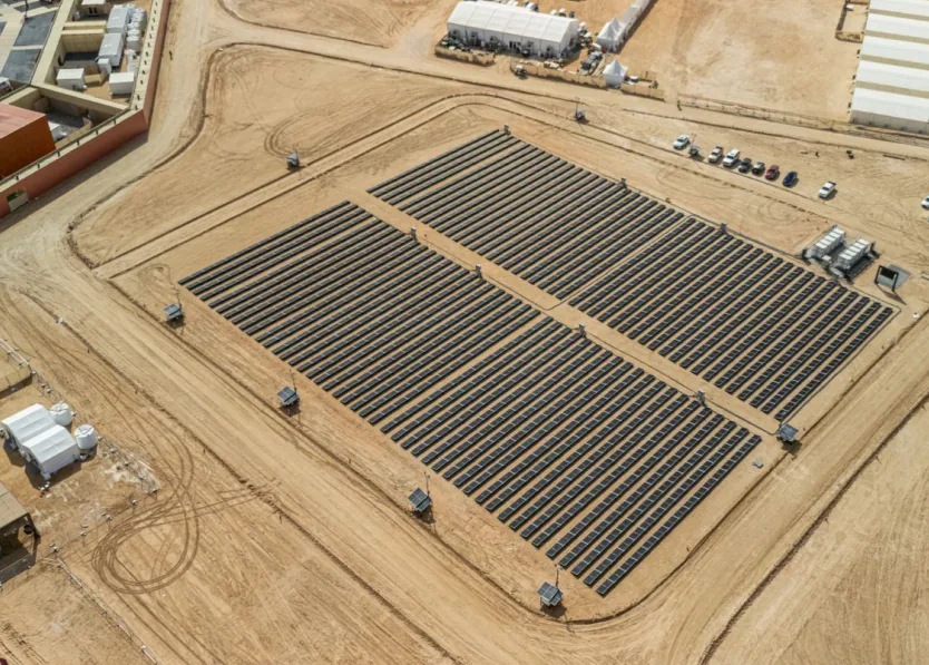
Liwa installation overview · project photography.
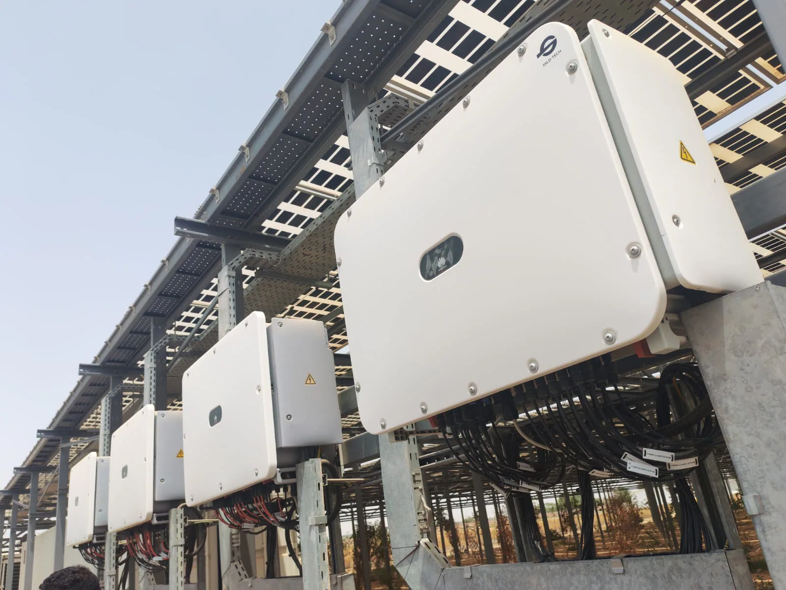
Installed inverter lineup · project photography.
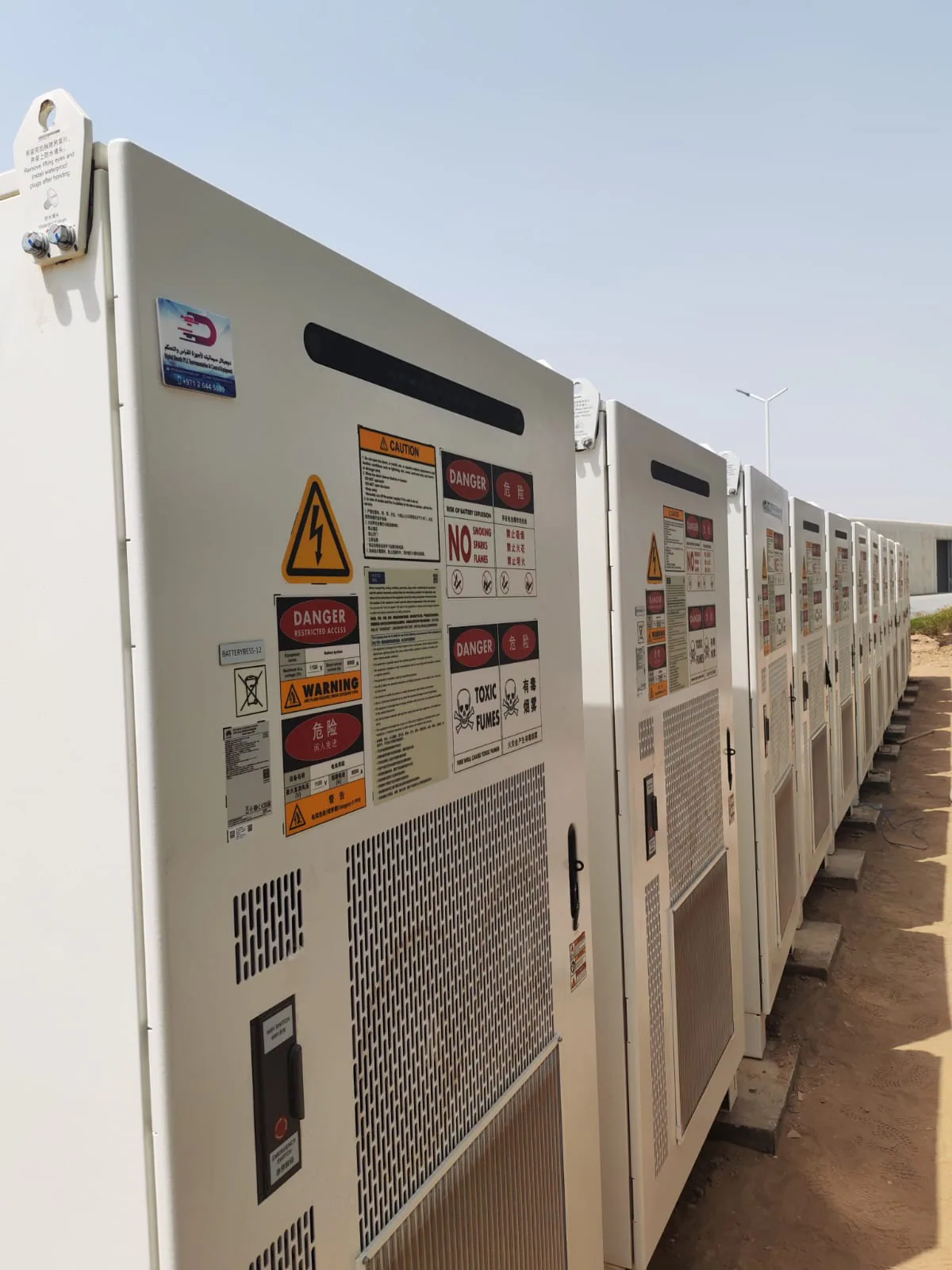
Installed BESS cabinets · project photography.
SOLUTIONS / ENGINEERING / SOFTWARE
Start with the load, the available sources and the operating duty. We bring generation, storage and industrial automation into one engineering conversation.
Solar generation supports site demand alongside the utility. Export and zero-export arrangements follow the approved connection scheme.
A standard grid-tied system does not automatically provide outage backup.Generation and storage are selected around a site operating without the public grid, including generator integration where required.
Load steps, usable battery energy and recharge requirements shape the design.Combine sources and storage around the application. DC-coupled and AC-coupled arrangements offer different integration approaches.
Backup, generator support and grid-forming capability depend on the selected equipment.FROM SITE SURVEY TO HANDOVER
Tell us your site location, operating hours, available sources and backup needs.
Request a consultation